Application Field
The electro-hydraulic servo dynamic fatigue testing machine (referred to as the testing machine) is mainly used to test the dynamic characteristics of metal, non-metal and composite materials at room temperature (or high and low temperature, corrosive environment). The testing machine can perform the following tests:
Tensile and compression test
Crack growth test
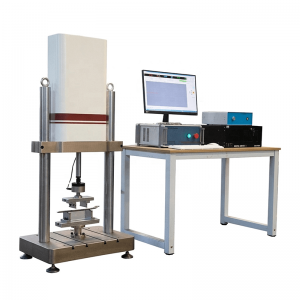
The closed-loop servo control system composed of electric controller, servo valve, load sensor, displacement sensor, extensometer and computer can automatically and accurately control the test process, and automatically measure test parameters such as test force, displacement, deformation, torque, and angle.
The testing machine can realize sine wave, triangle wave, square wave, sawtooth wave, anti-sawtooth wave, pulse wave and other waveforms, and can perform tensile, compression, bending, low-cycle and high-cycle fatigue tests. It can also be equipped with an environmental test device to complete environmental simulation tests at different temperatures.
The testing machine is flexible and convenient to operate. The moving beam lifting, locking, and specimen clamping are all completed by button operations. It uses advanced hydraulic servo drive technology to load, high-precision dynamic load sensors and high-resolution magnetostrictive displacement sensors to measure the force of the specimen. Value and displacement. The all-digital measurement and control system realizes PID control of force, deformation and displacement, and each control can be switched smoothly. , The test software works in the WINDOWS XP/Win7 Chinese environment, with powerful data processing functions, test conditions and test results are automatically saved, displayed and printed. The test process is fully integrated into computer control. The test machine is an ideal cost-effective test system for scientific research institutes, metallurgical construction, national defense and military industry, universities, machinery manufacturing, transportation and other industries.
Specifications
|
Model |
PWS-25KN |
PWS-100KN |
|
Maximum test force |
25kN |
100kN |
|
Test force resolution code |
1/180000 |
|
|
Test force indication accuracy |
within ±0.5% |
|
|
Displacement measurement range |
0~150(±75)(mm) |
|
|
Displacement measurement component |
0.001mm |
|
|
Relative error of displacement measurement indication value |
within ±0.5% |
|
|
Acquisition frequency |
0.01~100Hz |
|
|
Standard test frequency |
0.01-50Hz |
|
|
Test waveforms |
Sine wave, triangle wave, square wave, half sine wave, half cosine wave, half triangle wave, half square wave, etc. |
|
|
Test space (without fixture) mm |
1600(can be customized) |
|
|
Internal effective width mm |
650(can be customized) |
|
Standard
1) GB/T 2611-2007 "General Technical Requirements for Testing Machines"
2) GB/T16825.1-2008 "Inspection of Static Uniaxial Testing Machine Part 1: Inspection and Calibration of Force Measuring System of Tensile and (or) Compression Testing Machine"
3) GB/T 16826-2008 "Electro-hydraulic Servo Universal Testing Machine"
4) JB/T 8612-1997 "Electro-hydraulic Servo Universal Testing Machine"
5) JB9397-2002 "Technical Conditions of Tension and Compression Fatigue Testing Machine"
6) GB/T 3075-2008 "Metal Axial Fatigue Test Method"
7) GB/T15248-2008 "Axial Constant Amplitude Low Cycle Fatigue Test Method for Metallic Materials"
8) GB/T21143-2007 "Uniform Test Method for Quasi-Static Fracture Toughness of Metallic Materials"
9) HG/T 2067-1991 rubber fatigue testing machine technical conditions
10) ASTM E466 Standard Test of Kic for Linear Elastic Plane Strain Fracture Toughness of Metallic Materials
11) ASTM E1820 2001 JIC test standard for a measure of fracture toughness
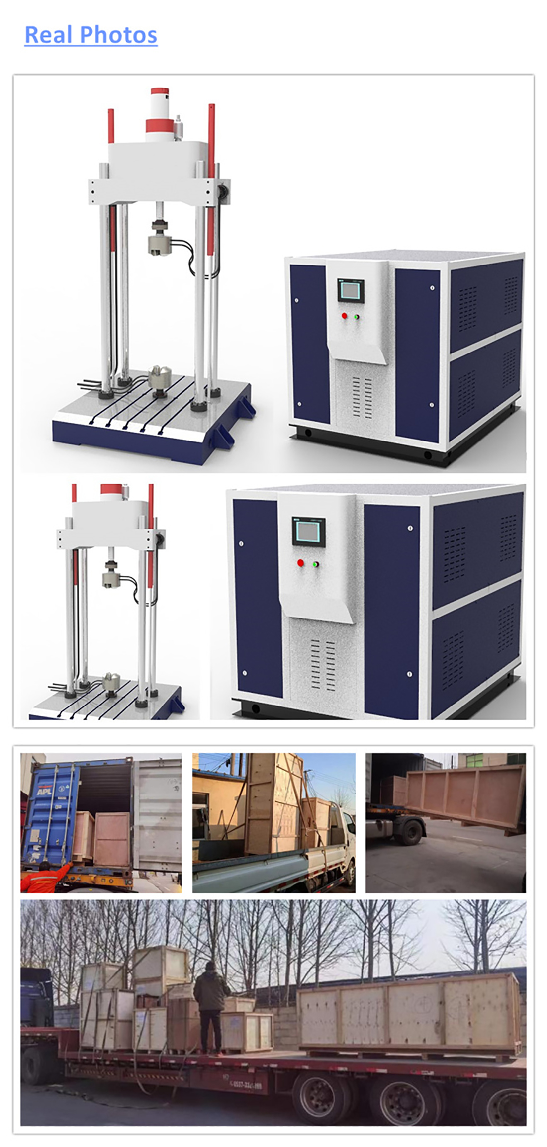
Key Features
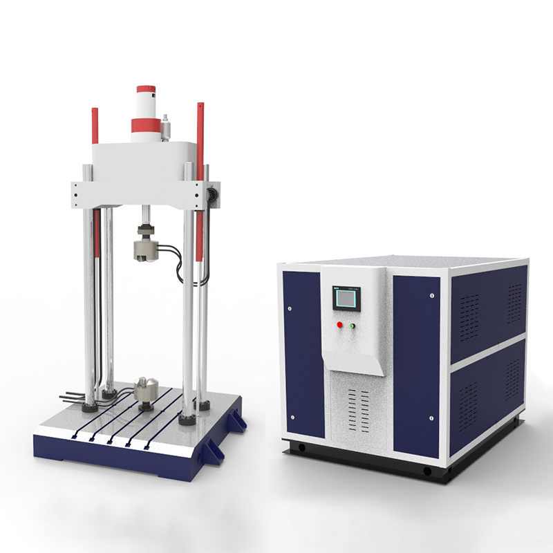
1 Host: The host is composed of a loading frame, an upper-mounted axial linear actuator assembly, a hydraulic servo oil source, a measurement and control system, and test accessories.
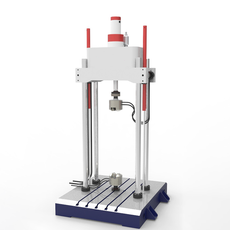
2 Host loading frame:
The loading frame of the main machine is composed of four uprights, movable beams and a workbench to form a closed loading frame. Compact structure, high rigidity and fast dynamic response.
2.1 Axial bearing capacity: ≥±100kN;
2.2 Movable beam: hydraulic lifting, hydraulic locking;
2.3 Test space: 650×1600mm<width×height>;
2.4 Load sensor: (Qianli)
2.4.1 Sensor specifications: 100kN
2.4.2 Sensor linearity: ±0.1%;
2.4.3 Sensor overload: 150%.
3 Hydraulic servo axial linear actuator:
3.1 Actuator assembly
3.1.1 Structure: adopt integrated design of servo actuator, servo valve, load sensor, displacement sensor, etc.
3.1.2 Features: Integrated base installation shortens the load chain, improves the rigidity of the system, and has good lateral force resistance.
3.1.3 Acquisition frequency: 0.01~100Hz (the test frequency generally does not exceed 70Hz);
3.1.4 Configuration:
a. Linear actuator: 1
I. Structure: Double rod double acting symmetrical structure;
II. Maximum test force: 100 kN;
III. Rated working pressure: 21Mpa;
IV. Piston stroke: ±75mm; Note: Set hydraulic buffer zone;
b. Electro-hydraulic servo valve: (imported brand)
I. Model: G761
II. Rated flow: 46 L/min 1 piece
III. Rated pressure: 21Mpa
IV. Working pressure: 0.5~31.5 Mpa
c. One magnetostrictive displacement sensor
I. Model: HR series
II. Measuring range: ±75mm
III. Resolution: 1um
IV. Non-linearity: <±0.01% of full scale>
4 Hydraulic servo constant pressure oil source
The pumping station is a standardized pumping station with a modular design. Theoretically, it can be cascaded into a large pumping station with any flow, so it has good scalability and flexible use.
l·Total flow 46L/min, pressure 21Mpa. (Adjusted according to experimental requirements)
l·The total power is 22kW, 380V, three-phase, 50hz, AC.
l·The pump station is designed and manufactured according to the standard modular design, with mature technology and stable performance; it is equipped with a relay voltage stabilizing module, which is connected with the actuator.
l·The pumping station is composed of oil pumps, motors, high and low pressure switching valve groups, accumulators, oil filter s, oil tanks, piping systems and other parts;
l·The filtration system adopts three-stage filtration: oil pump suction port, 100μ; oil source outlet, filtration accuracy 3μ; relay voltage regulator module, filtration accuracy 3μ.
l·The oil pump is selected from German Telford internal gear pump, which adopts involute internal gear meshing transmission, low noise, excellent durability and long life;
l·The oil pump motor unit is equipped with a damping device (choose damping pad) to reduce vibration and noise;
l·Use high and low pressure switch valve group to start and stop the hydraulic system.
l·Fully enclosed standard servo fuel tank, the volume of the fuel tank is not less than 260L; it has the functions of temperature measurement, air filtration, oil level display, etc.;
l·Flow rate: 40L/min, 21Mpa
5. 5 Forced to add specific (optional)
5.5.1 Hydraulic forced clamping chuck. set;
l·Hydraulic forced clamping, working pressure 21Mpa, meets the requirements of high and low frequency fatigue test of material tension and compression at zero crossing.
l·The working pressure can be adjusted, the adjustment range is 1MP-21Mpa;
l·Open structure, easy to replace the jaws.
l·With self-locking nut, connect the load sensor on the upper part of the main engine and the piston of the lower actuator.
l·Clamping jaws for round specimens: 2 sets; clamping jaws for flat specimens: 2 sets; (expandable)
5.5.2 One set of aids for compression and bending tests:
l·One set of pressure plate with diameter φ80mm
l·A set of three-point bending aids for crack growth fatigue test.